


Are All XLR Cables Balanced? The Complete Guide to Audio Signal Integrity
XLR cables show up everywhere in professional audio. Recording studios, live concerts, radio stations – you'll find these sturdy connectors in use. But here's something that catches many audio professionals off guard: Are all XLR cables balanced?
The answer is no – not all XLR cables are balanced. While manufacturers designed XLR connectors for balanced audio, having an XLR connector doesn't guarantee you're getting a balanced signal. This mix-up can cause noise problems and hurt your audio quality.
This guide breaks down the technical facts about XLR cables. We'll look at when they're truly balanced and when they're not. You'll also learn how to make smart decisions for your audio system. Whether you're building a home studio or running sound for live shows, these details matter for keeping your signal clean.
Understanding Balanced Audio: How Noise Rejection Actually Works
To know when XLR cables are truly balanced, we need to understand what makes audio transmission "balanced" first. Balanced audio isn't marketing speak – it's a smart engineering fix for a real problem in audio transmission.
The Three-Wire System: Hot, Cold, and Ground Setup
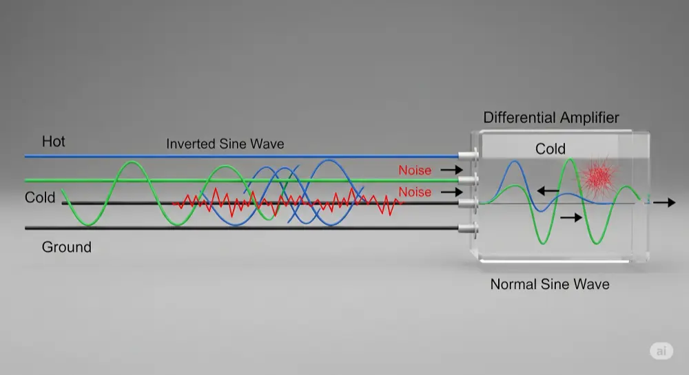
Balanced audio cables use three wires instead of the two-wire setup you'll find in unbalanced cables. Here's the breakdown:
Hot Wire (Pin 2): Carries the original audio signal in normal phase Cold Wire (Pin 3): Carries the same audio signal, flipped 180 degrees Ground Wire (Pin 1): Provides the reference point and connects to cable shielding
This double-signal approach might look unnecessary, but it's actually brilliant. By sending the same information down two paths – one normal, one flipped – the system sets up amazing noise rejection.
The ground wire does double duty: it gives both signals a stable reference point and connects the cable's shield to equipment, adding extra protection against outside interference.
Common-Mode Rejection: The Science Behind Noise Cancellation
The real magic of balanced audio happens through Common-Mode Rejection (CMR). Here's what occurs when your XLR cable picks up interference from power lines, wireless devices, or other electronics:
1.Interference Gets In: Outside noise hits both the hot and cold wires equally – this is "common-mode noise"
2.Signal Gets Processed: At the receiving end, a differential amplifier compares both signals. It flips the cold signal back to its original phase, making hot and cold signals match again
3.Noise Gets Canceled: Since the noise was picked up the same way on both wires, when the cold signal gets flipped, its noise becomes opposite to the hot signal's noise. When both signals combine, the noise cancels out while the audio signal gets twice as strong
We measure how well this works with the Common-Mode Rejection Ratio (CMRR), shown in decibels (dB). Higher CMRR numbers mean better noise rejection – professional audio gear typically hits CMRR ratings of 60dB or more.
This smart noise rejection system lets balanced XLR cables keep signals clean over distances beyond 100 feet, making them essential for professional audio work.
XLR Connector Basics: Why Pros Choose This Standard
XLR connectors earned their reputation as the professional audio standard through smart electrical design and tough physical construction.
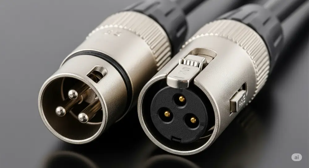
Standard 3-Pin XLR Layout
The Audio Engineering Society (AES) set the industry-standard setup, known as "Pin-2 Hot":
•Pin 1: Ground/Shield – connects to cable shielding and equipment ground
•Pin 2: Hot/Positive (+) – carries the normal-phase audio signal
•Pin 3: Cold/Negative (-) – carries the flipped-phase audio signal
This standard setup ensures all professional audio equipment works together. The three-pin design specifically supports the balanced audio transmission we just covered.
Some older or specialty equipment might use "Pin-3 Hot" setup, but this is rare in modern professional gear.
Physical Features That Set XLR Apart
Beyond the electrical side, XLR connectors offer several physical benefits:
Locking System: That distinctive latch prevents accidental unplugging – huge deal during live shows or important recordings
Strong Build: Metal housing and solid pin connections handle professional use, including lots of plugging and unplugging
Male/Female Design: Different connector types prevent wrong connections and make signal flow easy to follow
Shield Integration: The connector design works seamlessly with cable shielding, keeping signal quality intact from end to end
These physical features add up to XLR's reputation for reliability in tough professional situations.
When XLR Cables Are NOT Balanced: The Truth Many Don't Know
Here's where lots of audio folks get surprised: having XLR connectors doesn't guarantee balanced signal transmission. The basic rule is simple but often missed.
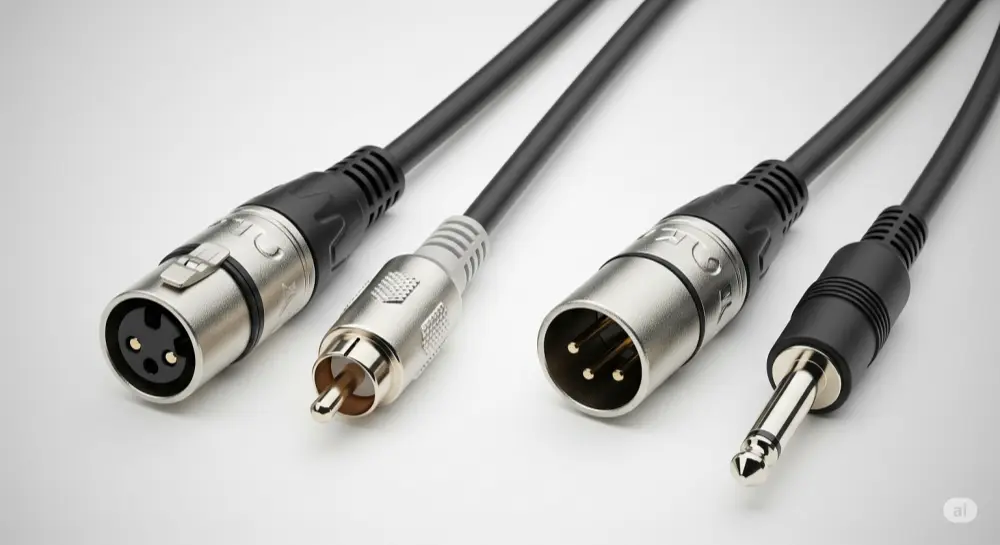
Adapter Cables: Where Balance Gets Lost
The golden rule for audio cables is: a cable's balance is only as good as its weakest part. When one end of your signal chain is unbalanced, the whole connection becomes unbalanced, XLR connector or not.
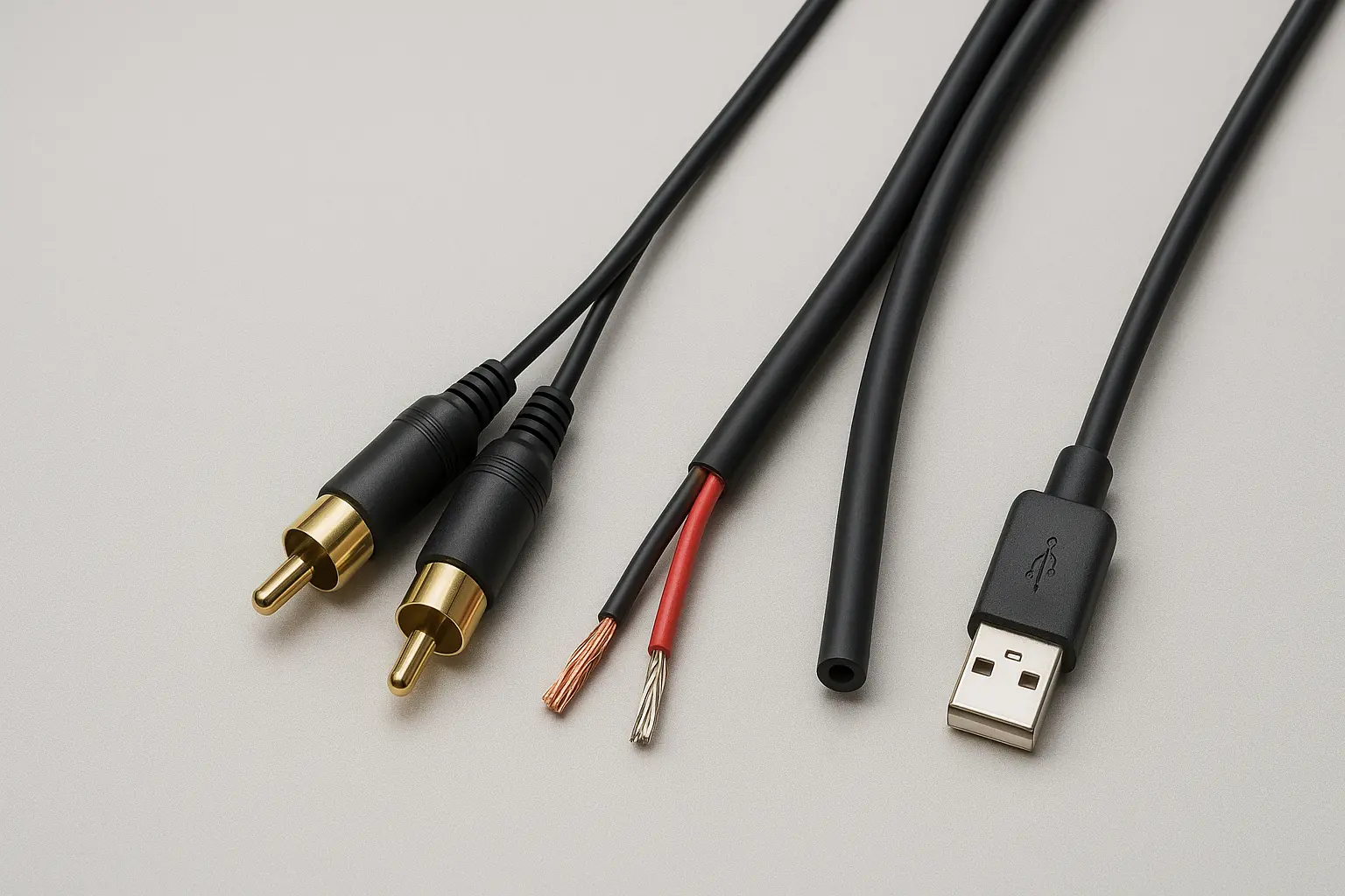
XLR to RCA Cables: These common adapter cables are perfect examples. Despite having XLR connectors on one end, they're basically unbalanced because RCA connectors only handle two-conductor (unbalanced) signals. Inside, these cables typically connect:
•XLR Pin 2 (hot) → RCA center pin
•XLR Pin 1 (ground) and Pin 3 (cold) → RCA outer ring
This wiring completely removes the noise rejection benefits of balanced transmission.
XLR to TS (1/4" Unbalanced) Cables: Similar to XLR-to-RCA cables, these adapters connect balanced XLR outputs to unbalanced TS inputs. The internal wiring follows the same idea:
•XLR Pin 2 → TS tip
•XLR Pin 1 and Pin 3 → TS sleeve
Some newer adapter cables leave Pin 3 unconnected to avoid stressing the output circuit, but you still end up with an unbalanced connection.
What This Means: These adapter cables solve connection problems but give up the noise rejection that makes balanced audio valuable for longer runs and electrically noisy places.
DMX Lighting vs. Audio XLR: Same Look, Different Job
One of the biggest mix-ups in audio/lighting work involves DMX cables. While they use identical 3-pin XLR connectors, DMX and audio XLR cables are built for totally different jobs.
Signal Differences:
•Audio XLR: Sends analog audio signals
•DMX XLR: Sends high-speed digital lighting control data
Important Impedance Differences:
•Audio XLR: 45-75 ohm characteristic impedance
•DMX XLR: 110-120 ohm characteristic impedance (AES/EBU digital standard)
Why You Can't Mix Them: Using the wrong cable type creates impedance problems that cause:
•Audio cable for DMX: Signal bounce-backs, data errors, lighting fixture problems
•DMX cable for audio: Reduced signal quality, more interference susceptibility
Professional setups need proper cable selection – just because they plug together doesn't mean they work together electrically.
Other XLR Uses Beyond Audio
XLR connectors serve many purposes beyond audio:
•Intercom systems: Often use different pin setups
•Power applications: 4-pin and 5-pin XLR types for lighting and equipment power
•Digital protocols: Some digital audio standards use XLR connectors with different electrical specs
Each use might have different internal wiring, even with identical physical connectors.
How to Check if Your XLR Cables Are Actually Balanced
Knowing how to verify whether your XLR cables are truly balanced can save you from audio quality headaches later.
Visual Checks and Cable ID Methods
Cable Labels: Professional cables often show specs on the outer jacket:
•Look for "balanced," "low-impedance," or "microphone cable" marks
•DMX cables typically show "DMX," "110Ω," or "digital" labels
•Avoid cables marked as "patch cables" or showing impedance values outside 45-75Ω for audio
Connector Check: Look at both ends of the cable:
•True balanced cables have matching balanced connectors (XLR-to-XLR, TRS-to-TRS)
•Mixed connector types (XLR-to-RCA, XLR-to-TS) mean unbalanced operation
•Equipment labels often specify balanced vs. unbalanced inputs/outputs
Pro vs. Consumer Signs: Professional audio equipment typically has:
•XLR and TRS connectors for balanced signals
•Clear labeling of input/output types
•Specs mentioning CMRR or balanced operation
Testing XLR Cable Balance with Basic Tools

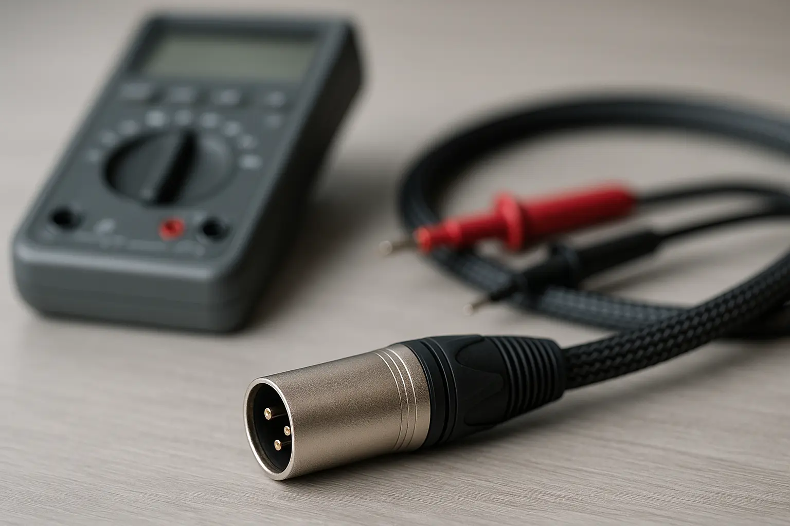
Multimeter Continuity Check:
1.Set your multimeter to continuity/resistance mode
2.Test Pin 1 to cable shield – should show connection
3.Test Pin 2 to Pin 3 – should show no connection (open)
4.Check Pin 1 to Pins 2 and 3 – should show no connection
Signal Path Check:
•In true balanced cables, Pins 2 and 3 should be separate from each other
•Ground (Pin 1) should connect to shield but stay separate from signal pins
•Any unexpected connections between signal pins suggest wiring problems
Professional Cable Testers: For regular testing, consider getting dedicated audio cable testers that can quickly check pin setups and signal quality.
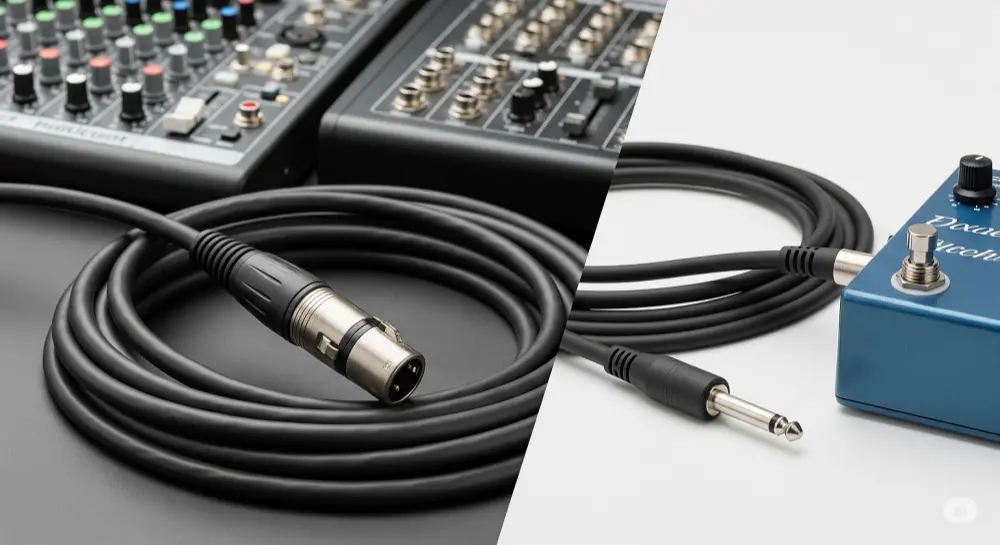
Choosing the Right Cable: XLR vs. TRS vs. Unbalanced Options
Understanding when each cable type works best can significantly impact your audio system's performance and your budget.
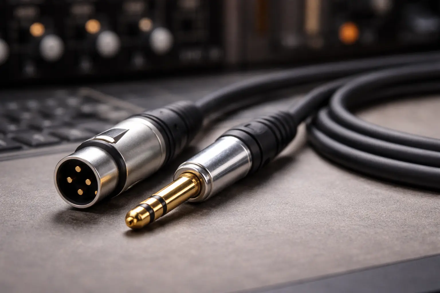
Balanced Cable Face-Off: XLR vs. TRS Performance
When both are properly wired for balanced operation, XLR and TRS cables offer the same signal quality and noise rejection. The choice between them often comes down to practical matters:
XLR Benefits:
•Better physical durability and locking connections
•Industry standard for microphones and professional equipment
•Better suited for portable and touring use
•Clearer signal flow indication (male/female orientation)
TRS Benefits:
•Smaller connector size
•Often cheaper for shorter runs
•Common on studio equipment and audio interfaces
•Easier to manage in tight connection spaces
Performance Match: Both cable types achieve the same noise rejection when used in fully balanced signal chains. The choice depends mainly on what you need and what equipment you have.
When Unbalanced Cables Work Just Fine
Despite balanced audio's benefits, unbalanced cables work perfectly well for many situations:
Short-Distance Uses (under 10 feet):
•Home recording setups with minimal interference
•Direct instrument connections to amps or interfaces
•Consumer audio equipment connections
Low-Interference Spots:
•Home settings with minimal electrical noise
•Dedicated audio rooms with proper electrical isolation
•Battery-powered portable recording setups
Budget Considerations:
•Unbalanced cables typically cost less
•Consumer equipment may not support balanced inputs/outputs
•Budget-conscious home studios with short cable runs
Signal Strength Benefits: In some short-distance applications, unbalanced signals can actually be stronger than balanced signals, since they don't go through the signal splitting required for balanced transmission.
Professional Cable Selection Guidelines
Making smart cable choices requires thinking about multiple factors beyond just connector type.
Application-Based Decision Making
Distance Requirements:
•Under 10 feet: Unbalanced cables work fine for most applications
•10-25 feet: Balanced cables recommended in electrically noisy environments
•Over 25 feet: Balanced cables essential for maintaining signal integrity
Environment Check:
•High interference: Stage lighting, wireless equipment, power amps nearby
•Moderate interference: Home studios with computer equipment
•Low interference: Isolated audio rooms, battery-powered setups
Equipment Compatibility:
•Professional gear: Usually supports both balanced and unbalanced
•Consumer equipment: Often limited to unbalanced connections
•Mixed setups: May need balanced-to-unbalanced adapters
Budget Optimization:
•Invest in balanced cables for long runs and critical connections
•Use quality unbalanced cables for short, low-interference applications
•Think about the total system cost, including any needed adapters or converters
Signal Chain Optimization Best Practices
Full System Analysis: Look at your entire signal path:
•Find the longest cable runs in your system
•Locate potential interference sources
•Decide which connections matter most to audio quality
Impedance Matching: Make sure all components in your signal chain match properly:
•Use appropriate cable impedance for your application
•Check equipment input/output specifications
•Think about the combined effect of multiple connections
Proper Grounding and Shielding:
•Keep shield connections continuous throughout your system
•Use star grounding topology when possible
•Avoid ground loops by following proper installation practices
Your XLR Cable Decision Framework
The answer to "Are all XLR cables balanced?" is definitely no. While XLR connectors are designed for balanced audio transmission, having an XLR connector doesn't guarantee you're getting balanced signal benefits.
Key Points:
•Connector type ≠ signal type: XLR connectors can carry unbalanced signals when connected to unbalanced equipment
•Weakest link rule: Your entire signal chain is only as balanced as its least balanced part
•Application matters: DMX and other non-audio uses put XLR connectors to completely different work
Your Next Steps:
1.Check your current setup: Find all XLR cables and verify their actual signal path
2.Look at both ends: Make sure both source and destination support balanced operation
3.Test when unsure: Use simple multimeter tests to verify cable wiring
4.Invest wisely: Focus on balanced cables for long runs and critical connections
Professional Advice: Always approach cable selection from a systems view. Think about your entire signal chain, environmental factors, and performance needs rather than making decisions based only on connector types.
Understanding these differences will help you build more reliable audio systems, avoid costly mistakes, and achieve the signal integrity that professional audio demands. Whether you're setting up a home studio or designing audio for a concert venue, this knowledge forms the foundation for making smart technical decisions.