


High Potential Test for Cable: 7 Practical Hipot Rules OEM Audio Buyers Use
2–3 SENTENCE SUMMARY
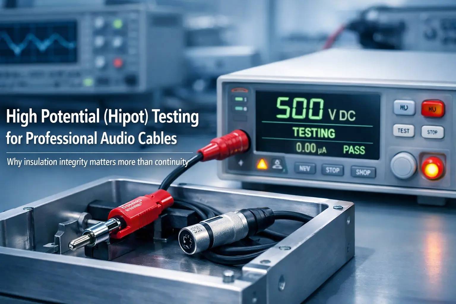
A high potential (Hipot) / dielectric withstand test is a controlled high-voltage check across a cable’s insulation to confirm it won’t arc, break down, or leak abnormally under electrical stress. OEM/ODM audio cable makers and installers rely on it because it finds hidden insulation and connector defects that a standard continuity test can miss. Done with the right settings and safety steps, it lowers returns, cuts noisy “mystery problems,” and reduces the chance of equipment damage.
KEY TAKEAWAYS
- A high potential test for cable checks insulation under stress and helps catch defects that continuity tests miss.
- Cables have capacitance, so current readings can be misleading if the method is not tuned.
- Published mic cable data can anchor your program target; one example lists 500V AC for 1 minute dielectric strength.
- DC Hipot often fits production screening well, but ramp control and discharge steps are non-negotiable.
- Weak insulation can show up as noise problems, not only hard shorts.
- Strong OEM programs write Hipot specs with clear test paths, limits, records, and failure handling rules.
INTRODUCTION (FOR OEM/ODM AUDIO CABLE CUSTOMERS)
If you’ve ever chased a random buzz in a studio, or had a cable fail only when the rig is under pressure, you already know the pattern: the cable looks fine, it passes continuity, and yet the system still misbehaves. Very often, the root cause sits in the one place that’s hardest to see—the insulation system, especially inside connectors.
A Hipot test is simple in concept: apply a higher-than-normal voltage across insulation and confirm the cable holds up. UL’s dielectric voltage withstand overview describes this as applying an extra-high voltage across insulation and checking whether the insulation barrier withstands it without breakdown. It also calls out practical traps like fast DC ramping and stored charge after DC tests, both of which matter on real production lines.
(Reference used in-line: UL Solutions dielectric withstand overview: https://code-authorities.ul.com/wp-content/uploads/sites/40/2015/02/UL_WP_Final_The-Dielectric-Voltage-Withstand-Test_v5_HR.pdf)
Internal link suggestion (for your site): /guides/xlr-pinout-phantom-power
DIRECT ANSWER — WHAT A “HIGH POTENTIAL / DIELECTRIC WITHSTAND” TEST IS AND WHY MAKERS AND INSTALLERS RELY ON IT
A high potential test for cable (Hipot) applies a specified high voltage between:
- conductor to conductor, and/or
- conductor to shield, and/or
- conductor to connector shell/housing
…then checks for breakdown, arcing, or leakage current behavior outside limits.
WHAT HIPOT CATCHES THAT CONTINUITY TESTING WON’T
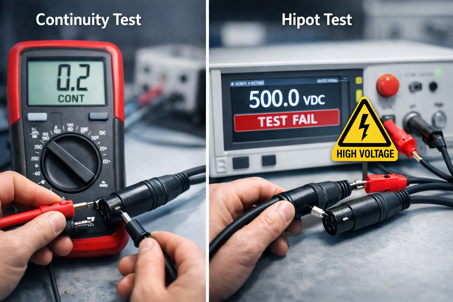
A continuity test answers only: “Is the intended path connected?” (Pin 2 to Pin 2, shield to shield, and so on). It usually uses low voltage and low energy. That’s great for opens and miswires, but it can’t stress the insulation in a way that exposes weak spots.
Hipot testing answers a different question: “Are unintended paths truly insulated under stress?” That means it can find:
- A stray copper strand near a solder joint (one tiny whisker can cause a batch issue)
- Flux residue or other contamination that forms a weak leakage path
- A nick or pinch in insulation from stripping, crimping, or handling
- Tight spacing inside a connector (pin-to-shell is a common risk point)
- Moisture sensitivity from storage or handling that lowers insulation resistance
UL also explains a key point about interpreting results: the goal is to confirm no breakdown under stress. A simple trip current number can be misleading in some cases, so the pass/fail logic should watch for true breakdown behavior (a sudden change), not just a number that may include normal dielectric effects.
A PRODUCTION-READY HIPOT WORKFLOW (GOOD FOR A CONTROL PLAN)
1) Fixture correctly (stable contacts, guarded electrodes, clean surfaces)
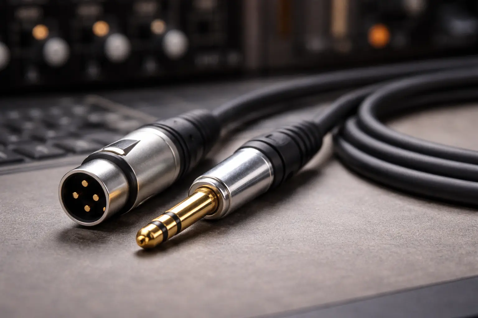
2) Choose test paths (include pin-to-shell for XLR/TRS assemblies)
3) Ramp up voltage at a controlled rate
4) Hold (dwell) for the set time
5) Measure current and, if available, arc events
6) Decide pass/fail
7) Discharge the cable after DC testing (treat it as charged until verified safe)
UL notes that DC testing can leave the DUT’s capacitance charged, so a discharge step is needed to reduce shock risk.
WHY CABLES ARE DIFFERENT IN HIPOT TESTING — CAPACITANCE AND CURRENT READINGS
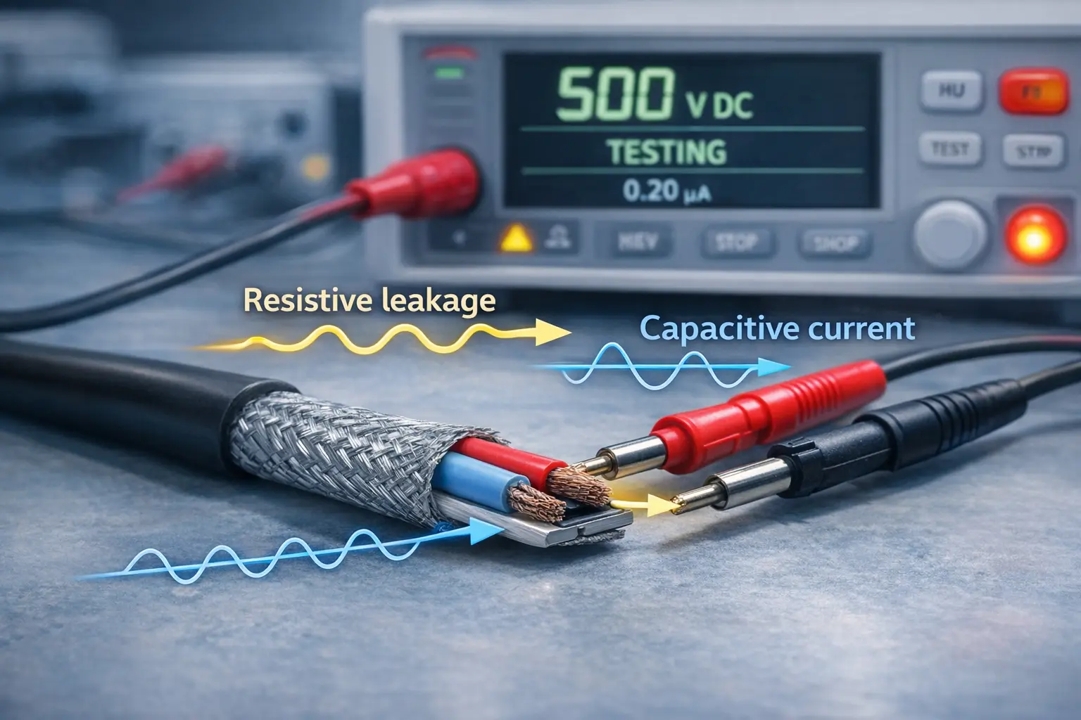
A cable behaves like a long capacitor: the conductors and shield act like plates, and the insulation is the dielectric. This matters because many testers report “total current,” and total current can include parts that are not true leakage.
Sefelec explains that in AC dielectric tests, the measured current is the vector sum of:
- Resistive (real) leakage current through insulation (the part linked to insulation health)
- Capacitive (reactive) current caused by the DUT’s capacitance (phase-shifted)
On capacitive DUTs like cables, reactive current can dominate. That can make it harder to spot meaningful insulation changes unless the test system separates the current components.
(Reference used in-line: Sefelec on real vs total current: https://www.sefelec.com/media/en/media/en/Upload/na0002en-1-0-real-capacitive-currents-707.pdf-707.pdf)
WHAT THIS MEANS FOR OEM AUDIO CABLE ASSEMBLIES
If you test finished audio assemblies (XLR/TRS patch cables) on a fast line:
- DC Hipot often reads “cleaner” after charging, because once the cable charges, the remaining current is mostly resistive leakage.
- AC Hipot can still be valid, but you must tune limits and ramp settings, or you’ll reject good product because reactive current looks high.
This is why two suppliers can run “the same voltage” but get very different yields. One is measuring and limiting the right thing. The other is fighting the physics of cable capacitance.
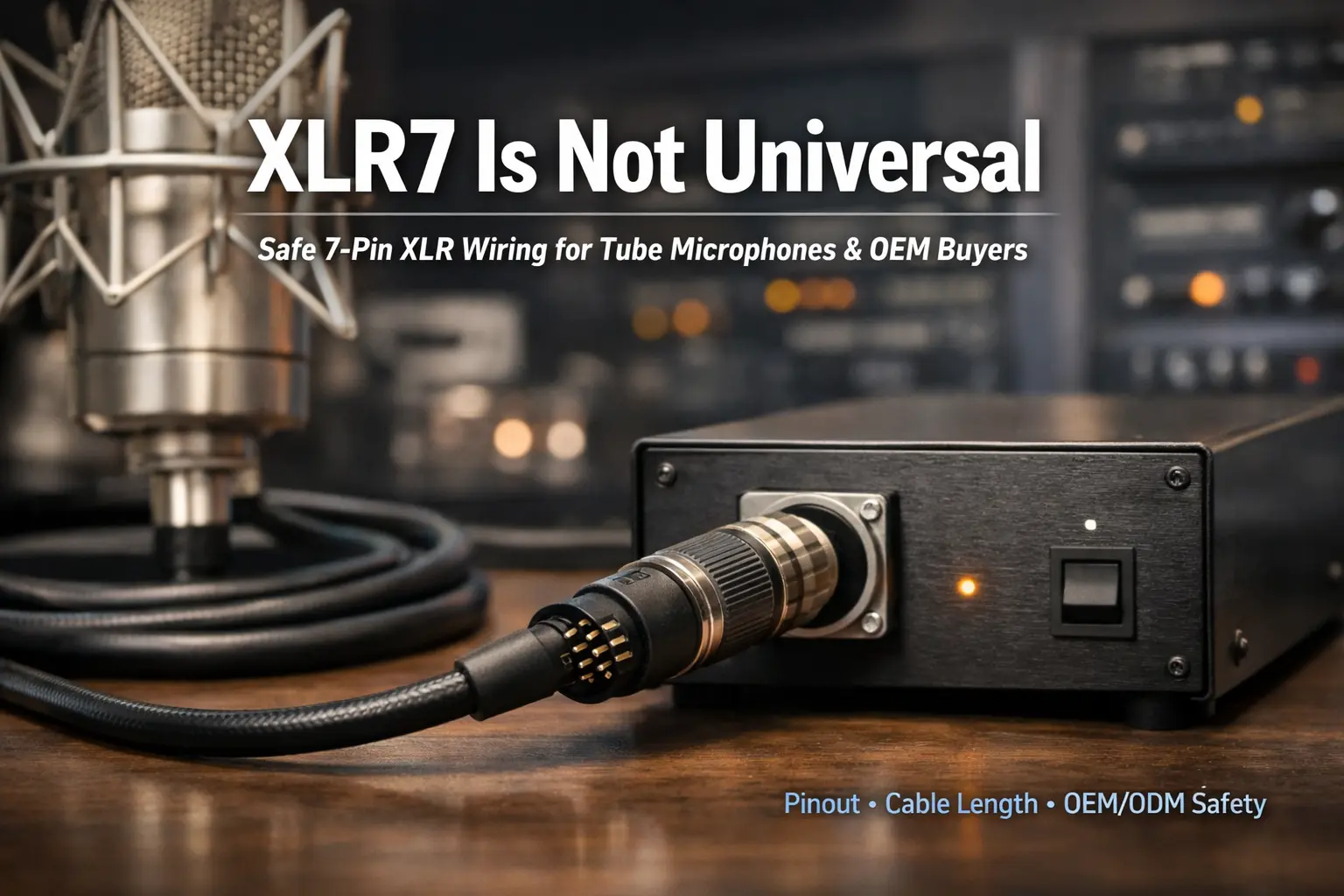
RELATED QUESTION 1 — WHAT IS THE STANDARD HIPOT TEST VOLTAGE FOR PROFESSIONAL XLR MICROPHONE CABLES?
There’s no single global “one number” that every XLR mic cable must use. Requirements vary by customer, market, and design. Still, you can anchor your spec to real published cable data.
For example, Canare lists a dielectric strength of 500V AC for 1 minute for its Star Quad microphone cable. That gives a real-world reference point when writing purchase specs.
(Reference used in-line: Canare Star Quad specs: https://canare.eu/products/cables/star-quad-microphone-cables-single/)
TURNING THAT INTO AN OEM-FRIENDLY PURCHASE REQUIREMENT
A practical purchase spec usually includes:
- Test mode: AC or DC (see next section)
- Voltage and time: anchored to cable data or a program target you agree on
- Test coverage: pin-to-pin, pin-to-shield, and pin-to-shell
- Limits: leakage limit and arc detection behavior
- Failure handling: quarantine + root-cause checks
If you use DC to match an AC withstand level, UL describes a common conversion rule: VDC is often set to about 1.414 times VAC (RMS) to match the AC peak stress. That matters when a program calls out AC in a spec but production prefers DC.
Brand expertise note for buyers: Don’t only ask “what voltage?” Ask “which paths?” A supplier can claim 500V testing but skip pin-to-shell, which is where many connector defects appear.
RELATED QUESTION 2 — SHOULD AC OR DC HIPOT TESTING BE USED FOR PROFESSIONAL AUDIO CABLE ASSEMBLIES?
For many audio cable assemblies, DC Hipot is often the practical production choice, mainly because it avoids ongoing reactive current after the cable charges. UL notes that once the DUT capacitance charges under DC, steady current can be much lower, which helps set tighter limits—if you manage ramp and discharge properly. Sefelec’s note supports the same idea from the current-component side.
AC VS DC HIPOT — QUICK COMPARISON FOR AUDIO ASSEMBLIES
Table: AC Hipot vs DC Hipot
Topic:
- Current reading on cables
AC Hipot: Includes reactive current (can be large)
DC Hipot: After charging, mostly resistive leakage
- Setup for fast production
AC Hipot: Can be trickier to tune limits
DC Hipot: Often easier to tune once ramp is stable
- Standards
AC Hipot: Sometimes requested/required by program
DC Hipot: Often allowed, but use correct equivalence where needed
- After-test safety
AC Hipot: Usually less stored charge than DC
DC Hipot: Stored charge is a real hazard—must discharge
WHERE PHANTOM POWER FITS (AND WHY HIPOT STILL MATTERS)
Phantom power is 48V, which sounds small, but it rides on the same conductors you’re testing. Triad Semiconductor’s explanation shows the classic layout: +48V applied equally to pins 2 and 3 through resistors, with return on pin 1. If workmanship lets voltage reach unintended paths (like shell contact), systems can behave badly.
(Reference used in-line: Phantom power basics: https://triadsemi.com/the-basics-of-phantom-power/)
RELATED QUESTION 3 — WILL PERFORMING A HIPOT TEST CAUSE PERMANENT DAMAGE OR DEGRADATION TO MY CABLES?
If the cable is good and the test settings are validated, Hipot testing is meant to be non-destructive. It’s a proof test: apply stress and confirm the insulation holds.
Where damage happens is when the cable is already defective. If a stray strand or contamination creates a tiny gap that arcs under high voltage, the fault site can carbonize and become permanent. That’s the test doing its job—rejecting a risky part before it reaches your customer.
TWO PRACTICAL RULES THAT KEEP HIPOT FROM TURNING INTO A HEADACHE
Rule 1: Control the ramp.
UL notes that fast ramping in DC tests can cause nuisance trips due to charging current. If you see that pattern, increasing ramp time can reduce false fails.
Rule 2: Don’t “test it until it passes.”
If a part fails, stop and investigate. Repeating stress on a borderline defect can make it worse and hide the real cause.
RELATED QUESTION 4 — IF A CABLE HAS ALREADY PASSED A STANDARD CONTINUITY TEST, WHY IS A HIPOT TEST STILL NECESSARY?
Because continuity doesn’t stress the insulation.
A continuity tester answers:
- “Is pin 2 connected to pin 2?”
- “Is the shield continuous?”
- “Is there an open or swap?”
Hipot answers:
- “Is pin 2 insulated from pin 1 under stress?”
- “Is pin 2 insulated from the connector shell?”
- “Will this cable arc when someone plugs it in during a live setup?”
UL’s discussion of dielectric withstand testing supports this purpose: it checks insulation strength under stress, which is a different job than low-voltage continuity checks.
A simple way to explain this to a purchasing team:
- Continuity = correct wiring
- Hipot = safe separation
You need both if you want fewer surprises.
RELATED QUESTION 5 — CAN AN INSULATION FAILURE, EVEN WITHOUT A HARD SHORT, HURT AUDIO SIGNAL QUALITY?
Yes. Audio problems don’t always come from hard shorts. A “soft” insulation issue can create leakage paths that unbalance a line and reduce noise rejection in a balanced system.
Balanced audio works best when both signal conductors “see” similar conditions to ground. If one conductor leaks more to shield/ground than the other (from contamination, moisture, or dielectric damage), you get an imbalance. That can show up as:
- hum or buzz pickup
- RF noise getting into the signal
- “computer noise” becoming audible in quiet chains
This is why many serious programs pair:
- Hipot for breakdown screening, and
- an insulation resistance (IR) requirement (or IR checks in audits) to catch weak insulation before it becomes a noise complaint.
A SPEC YOU CAN USE — HIPOT COVERAGE AND WORDING FOR OEM/ODM PURCHASE ORDERS
If you want a requirement that’s hard to “game,” write the spec with four parts: paths, voltage/time, limits, and records.
RECOMMENDED TEST PATHS FOR XLR MICROPHONE ASSEMBLIES
Test all of the following:
- Pin 2 ↔ Pin 1
- Pin 3 ↔ Pin 1
- Pin 2 ↔ Pin 3
- Pin 1 ↔ shell
- Pin 2 ↔ shell
- Pin 3 ↔ shell
SAMPLE PO / RFQ LANGUAGE (COPY AND EDIT)
- “Each finished assembly shall pass dielectric withstand (Hipot) testing on all pin-to-pin and pin-to-shell paths.”
- “Test shall use controlled ramp and dwell settings validated for this assembly type and length range.”
- “Failure handling: failed units shall be quarantined and checked for connector defects, contamination, insulation damage, and assembly errors.”
- “Supplier shall retain test records by lot/date and provide them on request.”
PARAMETER GUIDANCE (HOW TO SET IT WITHOUT DRAMA)
Use these ideas as a starting point, then validate:
- If your program spec calls out AC but production runs DC, use the UL AC-to-DC equivalence approach (about 1.414× VAC RMS for DC).
- Use a ramp that avoids nuisance trips on longer cables.
- Keep production screening short and consistent, then run longer audit/type tests to prove margin.
- Set leakage limits based on stable “good sample” behavior and your risk level, not on guesswork.
A practical approach many OEM teams use:
1) Test 30–50 known-good assemblies across your normal length range.
2) Record the steady readings under your chosen mode and ramp.
3) Set limits above normal spread but tight enough to catch outliers.
4) Lock the method into your control plan and keep calibration current.
TROUBLESHOOTING HIPOT FAILURES IN CABLE ASSEMBLIES
When a cable fails Hipot, the fastest way to solve it is to separate “connector problem” from “bulk cable problem.”
COMMON CONNECTOR-SIDE CAUSES
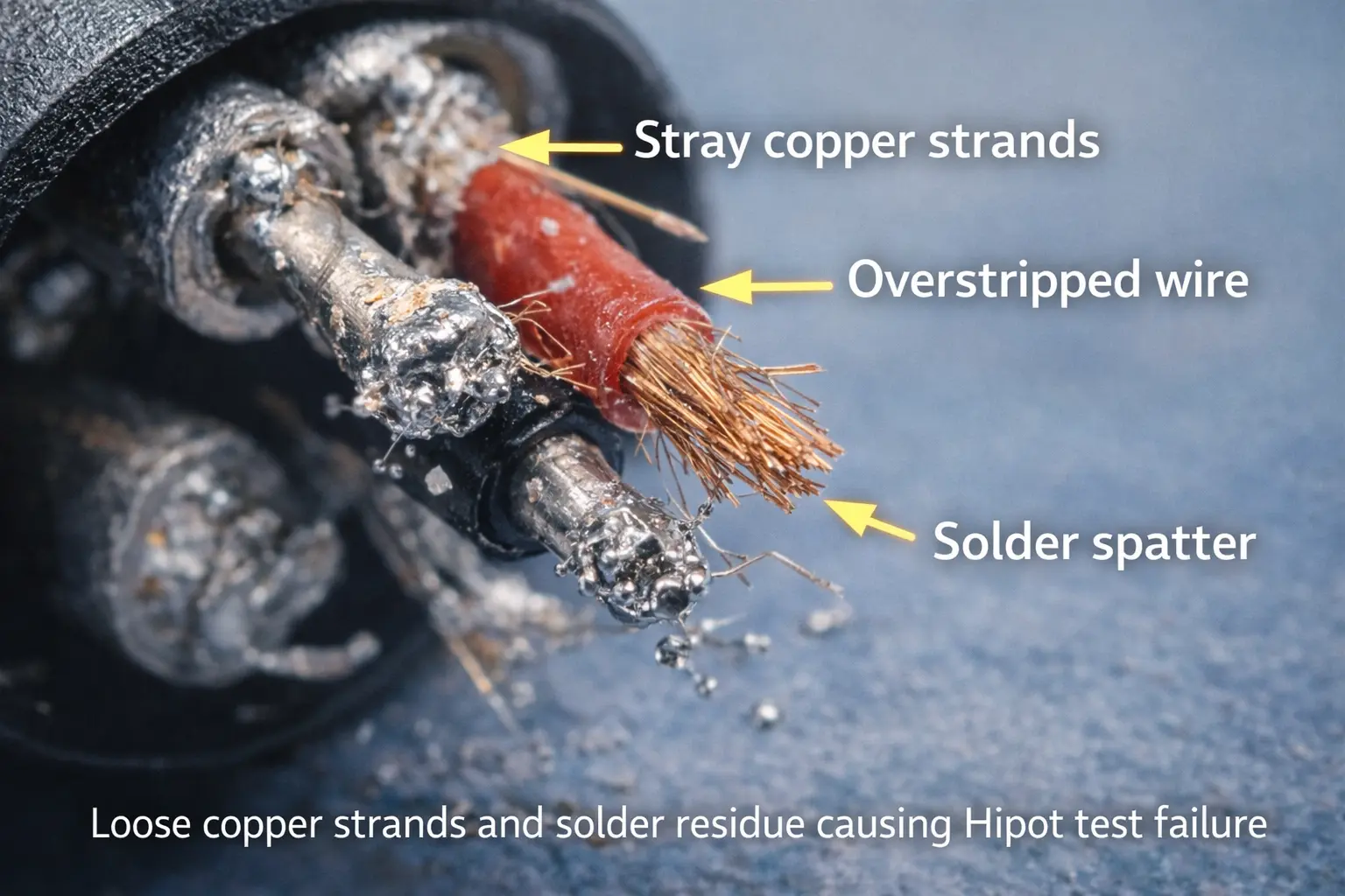
- A stray strand bridging close pads or pins
- Flux residue between pins or between pin and shell
- Too much stripped length, exposing conductor near the shell
- Poor strain relief that lets the conductor move and touch the shell
- Insulation shrink or heat damage during soldering
COMMON BULK CABLE CAUSES
- Cuts, crush, or pinch points from handling
- Abrasion through insulation under a clamp or grommet
- Contamination or moisture in storage (especially if packaging is weak)
A SIMPLE FAILURE-ANALYSIS PLAYBOOK
Step 1: Re-test at the same settings once (no repeats beyond that).
Step 2: If it fails again, isolate:
- Test the cable without connectors if possible, or
- Swap ends / test each end separately using a controlled fixture.
Step 3: Inspect:
- Look for whiskers and solder balls.
- Check strip length against work instructions.
- Check pin-to-shell clearance.
Step 4: Fix the process, not only the part:
- Update stripping tools, solder method, cleaning rules, and inspection points.
One thing to avoid: passing parts by relaxing limits without a reason. That usually creates more field failures later.
SAFETY STEPS YOUR SUPPLIER MUST FOLLOW (ESPECIALLY FOR DC HIPOT)
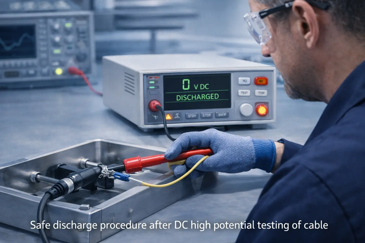
DC Hipot can leave a cable charged. Treat discharge as a required step, not an optional extra.
UL warns about stored charge and the need for a discharge step after DC testing. Megger’s guidance for HV DC dielectric testing also describes post-test grounding/shorting practice as part of safe work (the core idea applies even at lower voltages used on audio assemblies).
(Reference used in-line: Megger HV DC dielectric test sets PDF: https://us.megger.com/-/media/megger/documents/product-documents/d-dc-dielectric-test-sets.pdf)
Buyer audit checklist:
- Tester model and calibration records
- Guarding/interlocks on the station
- Written discharge method (and how it’s verified)
- Clear retest rules (no repeated “try again” passes)
- Lot/date traceability and record retention
BRAND EXPERTISE — WHAT STRONG OEM PROGRAMS DO DIFFERENTLY
If you’re building a brand, the goal isn’t “we own a Hipot tester.” The goal is “our process keeps defects from slipping through.”
Three habits show up in strong programs:
1) Connector area control: strip length, whisker prevention, cleanliness rules, and pin-to-shell checks are treated as daily basics.
2) Two layers of testing: a fast 100% screen for every cable, plus regular audit/type tests that prove the design margin over time.
3) Trend watching: not only pass/fail. When leakage or IR trends drift, teams act early before customers feel it.
CITTIONS (5)
1) UL Solutions — The Dielectric Voltage Withstand Test (PDF)
https://code-authorities.ul.com/wp-content/uploads/sites/40/2015/02/UL_WP_Final_The-Dielectric-Voltage-Withstand-Test_v5_HR.pdf
2) Sefelec — Hipot Tests: Real current and total current (PDF)
https://www.sefelec.com/media/en/media/en/Upload/na0002en-1-0-real-capacitive-currents-707.pdf-707.pdf
3) Canare — Star Quad Microphone Cables (spec page showing dielectric strength)
https://canare.eu/products/cables/star-quad-microphone-cables-single/
4) Triad Semiconductor — The Basics of Phantom Power
https://triadsemi.com/the-basics-of-phantom-power/
5) Megger — High Voltage DC Dielectric Test Sets (PDF)
https://us.megger.com/-/media/megger/documents/product-documents/d-dc-dielectric-test-sets.pdf