


How to Wire XLR Connectors: A Complete Audio Cable Guide
If you work with professional audio, you know custom XLR cables are a must-have. Store-bought cables break when you need them most, and they never come in the exact lengths you need for your setup. Learning to wire XLR connectors yourself saves money and gives you reliable cables built to your specifications.
This guide walks you through the same techniques used in professional studios and live sound setups. You'll learn balanced audio basics, proper soldering methods, and how to test your finished cables. By the time you're done, you'll be building XLR cables that match or beat anything you can buy.
XLR Wiring Basics: How Balanced Audio Works
Standard XLR Pinout: Understanding Pins 1, 2, and 3
The Audio Engineering Society (AES) sets the industry standard for XLR pin assignments. This keeps equipment from different manufacturers compatible with each other.
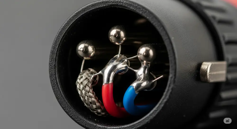
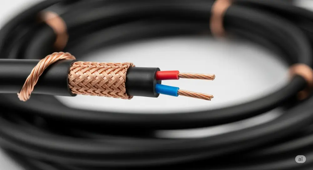
Pin 1: Ground/Shield Connection Pin 1 connects to your cable's braided shield. This shield acts like a protective cage around your signal wires, catching electromagnetic interference and radio frequency noise before it can mess with your audio.
Pin 2: Positive/"Hot" Signal Pin 2 carries your main audio signal - the "hot" or positive conductor. This wire sends your original audio exactly as it comes from the source.
Pin 3: Negative/"Cold" Signal Pin 3 carries an inverted copy of your signal, flipped 180 degrees out of phase with Pin 2. This "cold" or negative conductor is what makes balanced audio special.
Easy Way to Remember Many audio engineers use this memory trick: X (earth/ground for Pin 1), L (live/hot for Pin 2), R (return/cold for Pin 3).
Note: Some older American gear used "Pin 3 hot," but today's AES standard of "Pin 2 hot" is what everyone uses. Always check your equipment specs, especially with vintage gear.
Why Balanced XLR Cables Beat Unbalanced Connections
Balanced audio is one of the smartest solutions to noise problems in pro audio. The way it rejects interference makes XLR cables essential when you need clean signals.
How Balanced Audio Works Your original audio signal gets split into two identical copies. One copy goes down Pin 2 unchanged. The second copy gets flipped 180 degrees and travels down Pin 3. Both signals pick up the same interference as they travel through the cable.
Noise Cancellation Magic Here's where it gets clever: the receiving equipment flips the Pin 3 signal back to its original polarity and combines it with Pin 2. Now your original audio signals are back in phase and add together, becoming twice as strong (6dB gain). Meanwhile, the identical noise on both wires is now out of phase and cancels itself out.
Distance and Performance Benefits This noise rejection lets properly wired XLR cables run over 300 feet without problems. Compare that to unbalanced cables, which start picking up noise after 25 feet and become unusable for long runs in pro environments.
Balanced audio really shines in tough RF environments like concert venues and broadcast facilities. While unbalanced connections pick up cell phone interference and lighting noise, a well-made XLR cable stays clean even in electrically noisy places.
Tools You Need for XLR Soldering
Essential Equipment Checklist
Building professional XLR cables requires the right tools. Good tools make the job easier and help your cables last longer.
Core Soldering Tools:
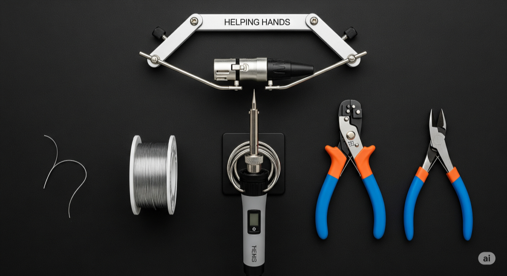
● Soldering Iron: 30-40W with temperature control works best for audio connectors. Avoid high-wattage irons that can melt plastic parts
● Solder: 60/40 rosin-core solder is the pro standard. 63/37 eutectic flows smoother but costs more
● Wire Strippers: Get precision strippers made for small-gauge wire to avoid damaging conductors
● Flush Cutters: Quality cutters give clean cuts without deforming the wire
● Helping Hands: A third-hand tool or small vise holds connectors steady while you solder
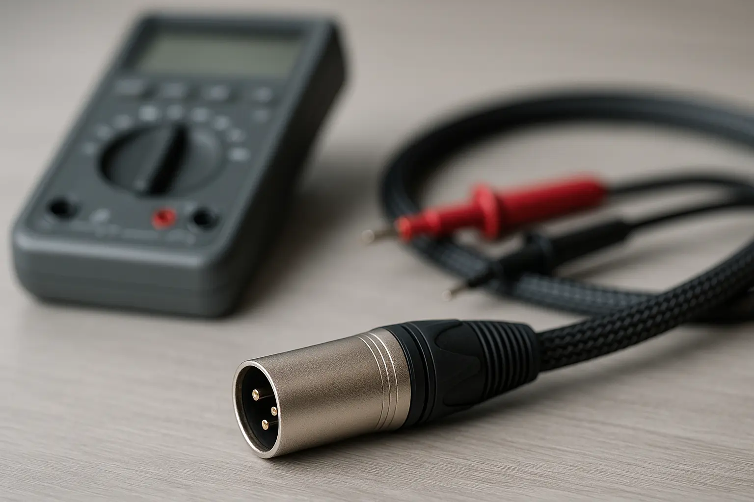
● Multimeter: Digital meter with continuity beep for testing your finished cables
Safety Gear: Always wear safety glasses to protect against solder splatter. Work in a well-ventilated area to avoid breathing flux fumes. Keep a damp sponge handy for cleaning your iron tip - this keeps heat transfer optimal and solder flowing smoothly.
Workspace Setup: Good lighting and easy tool access make everything easier. A proper soldering mat protects your work surface and gives you a clean, static-free work area.
Choosing Quality Cable and Connectors
Your raw materials directly affect how well your finished cables perform and how long they last. Pro-grade components cost more upfront but give you better reliability and easier assembly.
Professional Cable Options: Cables like Mogami 2534, Canare L-4E6S, and Gotham GAC-3 are the gold standard in pro audio. These feature star-quad geometry for better noise rejection, low capacitance for extended frequency response, and flexible jackets that handle repeated coiling and movement.
Look for conductor gauge (usually 22-24 AWG), shield coverage (95%+ is best), and jacket material. PVC jackets offer good flexibility and durability for most uses, while polyurethane stays flexible in cold weather.
Connector Quality Counts: Neutrik (NC3MXX/NC3FXX series) and Switchcraft (A3M/A3F series) connectors are the professional choice. These brands offer solid strain relief, precise machining for consistent fit, and gold-plated contacts for long-term reliability.
Quality indicators include solid metal construction, smooth locking mechanisms, and well-designed strain relief. Skip generic connectors with poor tolerances and weak plastic parts - they often fail when you need them most.
Step-by-Step XLR Wiring Process
Cable Preparation: Getting Ready to Solder
Good cable prep is the foundation of every reliable XLR connection. Take your time with these steps - mistakes here affect everything that follows.
Don't Forget the Boot! Before cutting anything, slide the connector boot and strain relief parts onto your cable in the right order and direction. This is the most common mistake in DIY cable building - forgetting it means taking everything apart and starting over. Dry-fit all parts first to check their orientation.
Removing the Outer Jacket Strip about 1 inch (25mm) of outer jacket using a sharp blade or cable stripper. Score the jacket lightly all the way around, then make one cut lengthwise to your scoring mark. Peel away the jacket carefully - don't nick the braided shield underneath. Damaged shield strands create weak points and hurt noise rejection.
Preparing the Shield Push back the braided copper shield to expose the inner conductors. Gather all shield strands and twist them clockwise into one neat conductor for Pin 1. If your cable has a separate drain wire (a small bare wire running alongside the shield), twist it in with the shield strands. This combined conductor should be tight and neat for easier soldering.
Stripping Inner Conductors Strip 3-4mm (about 1/8 inch) of insulation from each signal conductor. Use quality strippers to get clean cuts without nicking the copper strands - this would weaken the connection. After stripping, lightly twist each conductor's strands into a neat, solid wire that's easier to handle.
Quality Check Before soldering, inspect your prepared cable end. Make sure no stray shield strands touch signal conductors, check that strip lengths fit properly in the connector's solder cups, and verify all conductors are neatly twisted and ready for tinning.
Tinning: Pre-Coating for Better Connections
Tinning is a pro technique that makes the difference between amateur and professional cable assembly. This pre-soldering step creates faster, stronger final connections while reducing heat stress on connector parts.
Why Tinning Matters Tinning coats both your prepared conductors and the connector's solder cups with a thin solder layer. This prep work lets the final soldering happen quickly with less heat, reducing the risk of melting plastic parts or creating weak joints.
Tinning Your Wires Heat each prepared conductor with your iron, then apply solder directly to the heated wire (not the iron tip). Done right, solder flows into the wire strands through capillary action, creating a solid, silver-colored tip. Tinned wire should look bright and smooth, not dull or grainy.
Preparing Solder Cups Add a small amount of solder to each connector pin's solder cup. Heat the cup from outside with your iron tip and add just enough solder to coat the cup bottom. Don't overfill, especially on female connectors where excess solder could drip into the socket.
Quality Check Properly tinned parts show smooth, bright silver surfaces with good solder flow. Avoid cold tinning (not enough heat) which creates dull, grainy surfaces that won't bond properly. Keep your iron tip clean with a damp sponge for best heat transfer and solder flow.
Soldering Male and Female Connectors
Understanding connector orientation and following a systematic approach gives you consistent, professional results. Remember that male and female connectors are mirror images when viewed from the back.
Connector Orientation from Behind When soldering, you're working from the connector's back. Female XLR connectors show Pin 1 at top right, Pin 2 at top left, and Pin 3 at bottom center. Male XLR connectors reverse this: Pin 1 at top left, Pin 2 at top right, and Pin 3 at bottom center. Always check the pin numbers marked on the connector rather than just going by visual patterns.
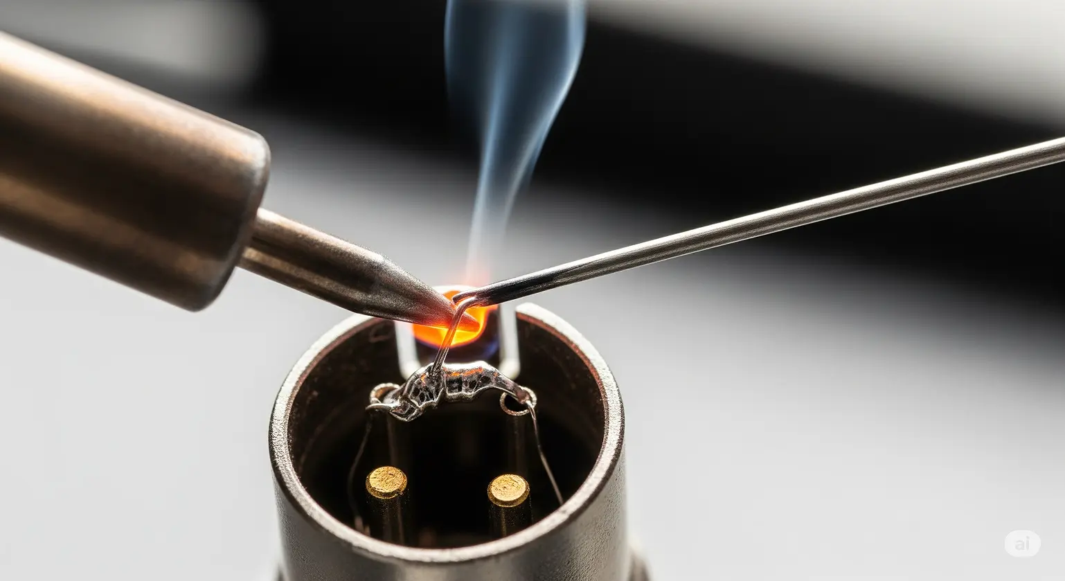
Soldering Order Start with Pin 1 (ground), soldering the twisted shield conductor to the right cup. The shield connection is usually the strongest mechanically and makes a good starting point. Next, solder Pin 2 (hot) with your positive conductor - typically red wire in color-coded cables. Finish with Pin 3 (cold) using your negative conductor, usually white, black, or blue depending on the cable maker.
Professional Soldering Method Put your iron tip on the outside of the solder cup, not directly on the solder or wire. When both cup and tinned wire reach the right temperature, the pre-applied solder melts and the tinned wire slides easily into the molten pool. Remove the iron and hold the connection perfectly still until the solder hardens to a shiny, concave finish.
Checking Your Work Good solder joints look smooth, shiny, and concave with complete wetting around both wire and cup. Avoid dull, grainy, or convex joints that indicate cold soldering. The wire should be completely surrounded by solder with no gaps. If a joint looks questionable, reheat it properly rather than hoping it holds.
Final Assembly and Strain Relief
Proper final assembly ensures your cable handles the mechanical stress of professional use. The strain relief system protects your solder joints from failure due to cable movement and pulling forces.
Assembly Steps Start by sliding the plastic strain relief chuck into position on the connector body. These plastic parts should grip the cable jacket firmly but not so tight as to deform it. Check alignment - misaligned strain relief creates stress points that cause early failure.
Shell and Boot Installation Slide the metal shell over the whole connector assembly, making sure it aligns with any keyways. Thread the connector boot onto the shell, but don't fully tighten yet. The boot should slide freely over the cable jacket without binding.
Activating Strain Relief As you tighten the boot onto the shell, the internal mechanism compresses the strain relief chuck around the cable jacket. Tighten firmly but don't overdo it - this can damage the cable jacket or stress the connector body. You want secure cable retention without damage.
Final Check Test your completed connector by gently pulling on the cable - there should be no movement at the solder joints, and the cable should feel securely anchored. The connector should mate and unmate smoothly with test equipment, and the locking mechanism should engage positively.
Testing and Troubleshooting XLR Cables
Testing with a Multimeter
Systematic testing with a digital multimeter gives you objective verification of your wiring work. This professional approach catches problems before they cause failures in the field.
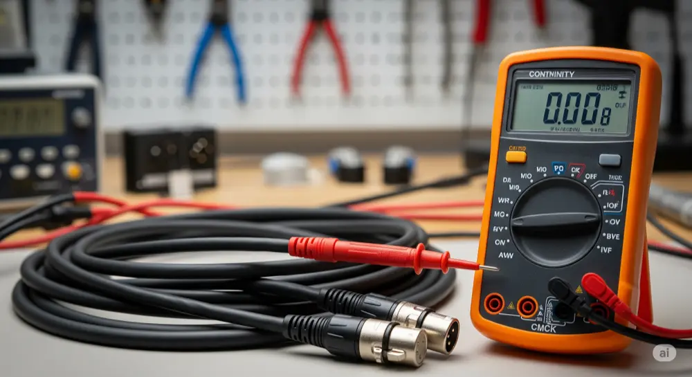
Setting Up Your Meter Set your digital multimeter to continuity mode, usually marked with a diode symbol or sound wave icon. In this mode, the meter beeps when it finds a complete electrical path between test probes. This audible feedback lets you watch the connectors while testing.
Continuity Testing Steps Put one probe on Pin 1 of the male connector and the other on Pin 1 of the female connector. You should hear a clear beep showing complete continuity through the shield/ground connection. Repeat this for Pin 2 to Pin 2 and Pin 3 to Pin 3. All three tests should produce clear beeps, confirming each conductor path is complete and properly connected.
Checking for Short Circuits Test for unwanted connections between different pins. Put probes on Pin 1 and Pin 2 of the same connector - there should be no beep. Repeat for Pin 1 to Pin 3 and Pin 2 to Pin 3 combinations. Any beep during these tests means a short circuit that must be fixed before using the cable.
Connector Shell Testing Many XLR connectors connect the metal shell to Pin 1 for extra shielding. Test between each connector's metal shell and Pin 1 to verify this connection if present. However, practices vary between manufacturers, so check connector documentation for specifics.
Keeping Records Professional setups benefit from systematic test documentation. Record test results for quality assurance and future troubleshooting reference. When building multiple cables, consistent testing ensures uniform quality across your entire cable inventory.
Common Problems and Solutions
Understanding typical failure modes and their symptoms helps you quickly diagnose and repair problem cables. Most XLR cable failures fall into predictable categories with characteristic symptoms and straightforward fixes.
Reversed Polarity Issues Reversed polarity happens when Pins 2 and 3 get swapped on one cable end. Symptoms include weak signal levels and phase cancellation when the cable is used with correctly wired cables in multi-microphone setups. The audio may sound thin or hollow, especially when signals are combined to mono or when using multiple microphones together. Fix this by desoldering and correctly rewiring the swapped pins.
Cold Solder Joint Problems Cold solder joints look dull, grainy, or cracked instead of smooth and shiny. These unreliable connections cause intermittent signal problems, crackling noises, and complete dropouts when the cable moves. Cold joints result from not enough heat during soldering or moving parts before the solder fully hardened. Fix by reheating the joint properly or completely desoldering and starting fresh.
Open Circuit Problems Complete signal loss usually means an open circuit - a broken conductor or completely failed solder joint. These failures often happen at stress points where cable enters the connector. Intermittent open circuits, where signal comes and goes with cable movement, usually mean wire strand breakage near the connector or a partially failed solder joint.
Ground Problems and Hum Pin 1 (ground) discontinuity allows noise pickup and can create ground loop conditions that show up as 50/60Hz hum in your audio signal. This problem is especially noticeable with phantom-powered microphones, which may not work at all with broken ground connection since phantom power needs a complete DC circuit through Pin 1.
Common Questions About XLR Wiring
What are the 3 wires in an XLR cable and what do they do?
An XLR cable has three conductors with specific jobs in balanced audio transmission. Pin 1 connects to the braided shield, providing ground reference and electromagnetic protection by capturing external interference and routing it safely to ground instead of letting it contaminate your audio signal. Pin 2 carries the positive "hot" audio signal, transmitting the original waveform exactly as it appears at the source. Pin 3 carries the negative "cold" signal, which is 180° out of phase with Pin 2, making possible the common mode rejection that makes balanced audio superior to unbalanced connections for professional use.
Does wire color matter when wiring XLR connectors?
While there's no universal color standard mandated by AES or other standards organizations, consistency between both cable ends is absolutely critical for proper polarity. Common industry conventions include red for Pin 2 (hot), white or black for Pin 3 (cold), and bare copper or green for Pin 1 (ground). Professional cable manufacturers like Mogami, Canare, and Gotham each have their preferred color schemes - Mogami typically uses red and white, while Canare often uses white and blue. The key rule is keeping identical wiring at both ends regardless of the specific colors used.
What's the difference between male and female XLR connectors in audio systems?
Male XLR connectors have protruding pins and typically connect to signal sources like microphones, instrument outputs, and equipment outputs. Female XLR connectors have sockets and typically connect to signal destinations like mixer inputs, amplifier inputs, and equipment inputs. This "outputs are male, inputs are female" convention prevents accidental feedback loops and follows established audio industry standards. The physical design also ensures proper signal flow direction and helps prevent wiring errors in complex audio systems.
Can you wire XLR connectors for unbalanced audio signals?
Yes, XLR connectors can carry unbalanced signals, though this gives up the main advantage of balanced audio - noise rejection capability. For connecting balanced XLR outputs to unbalanced inputs (like TS guitar jacks), the standard method wires Pin 2 to the tip (signal) and connects both Pin 1 (ground) and Pin 3 (cold) to the sleeve (ground). This prevents the cold signal from floating and potentially acting as an antenna for noise pickup. However, the resulting connection loses all common mode rejection benefits and should be kept as short as possible.
How do I test XLR cables without a multimeter?
While a multimeter provides the most reliable and thorough testing, basic functionality can be checked using a dynamic microphone connected to a mixer or audio interface. Dynamic microphones don't need phantom power, so they'll work even with minor ground issues. Connect the microphone through your test cable and listen for clean signal reproduction without crackling, dropouts, or unusual noise when moving the cable. However, this method won't catch polarity reversals, impedance mismatches, or subtle wiring errors that could cause problems in multi-microphone setups or with phantom-powered equipment.
Why do my XLR cables produce hum or buzzing sounds?
Hum and buzz in XLR cables typically indicate ground-related problems or electromagnetic interference pickup. Common causes include broken shield connections (Pin 1), damaged cable shielding, ground loops between connected equipment, or improper Pin 1 wiring. For phantom-powered condenser microphones, a broken ground connection will prevent the microphone from working entirely since phantom power needs a complete DC circuit through Pin 1. Environmental factors like proximity to power transformers, dimmer circuits, or RF sources can also contribute to noise pickup in improperly shielded or damaged cables.
What's the maximum length for XLR cables before signal gets worse?
Properly built balanced XLR cables can run 300+ feet (100+ meters) without significant signal loss, thanks to the common mode rejection properties of balanced audio transmission. However, practical considerations include increased cable capacitance causing high-frequency rolloff, potential ground loop issues in very long runs, and the cumulative effects of connector resistance. For critical applications over 200 feet, consider using low-capacitance cable designs, balanced line drivers, or digital transmission methods. The superior performance of balanced XLR over unbalanced connections becomes most apparent in these longer cable runs.
Can I repair a damaged XLR connector, or should I replace it?
Simple issues like loose strain relief, dirty contacts, or minor mechanical problems can often be repaired with basic maintenance. Contact cleaning with appropriate electronic cleaners (like DeoxIT) can resolve oxidation and contamination issues. However, damaged pins, cracked connector bodies, failed locking mechanisms, or compromised internal wiring typically require complete connector replacement. Given that professional XLR connectors cost $5-15, replacement is often more reliable and cost-effective than attempting complex repairs. The labor involved in disassembly, repair, and reassembly often exceeds the cost of new connectors while providing uncertain reliability.
Wrapping Up
Learning XLR connector wiring is an essential skill for audio professionals and serious enthusiasts. The techniques covered in this guide - from understanding balanced audio theory to systematic testing procedures - let you create reliable custom cables that often outperform commercial alternatives while providing exact lengths for your specific applications.
Success in professional XLR wiring depends on three basic principles: investing in quality components and tools, taking adequate time for proper preparation and technique, and implementing systematic testing to verify your work. Whether you're building a home studio, maintaining live sound equipment, or working in professional audio environments, these skills provide the foundation for reliable, high-performance audio systems.
Remember that cable reliability directly affects your professional reputation. A properly built XLR cable represents not just a connection between devices, but a critical link in your audio signal chain that must perform flawlessly when it matters most. The investment in learning these techniques pays off through reduced downtime, improved system reliability, and the satisfaction of creating professional-quality tools with your own hands.