


RCA Jacks: A Practical Guide for OEM and ODM Teams

Key Takeaways
- RCA jacksare female audio/video connectors first produced by Radio Corporation of America in the 1930s.
- They use a 3.175 mm center pin and an 8.25 mm outer ring; 75 Ω is preferred for video paths.
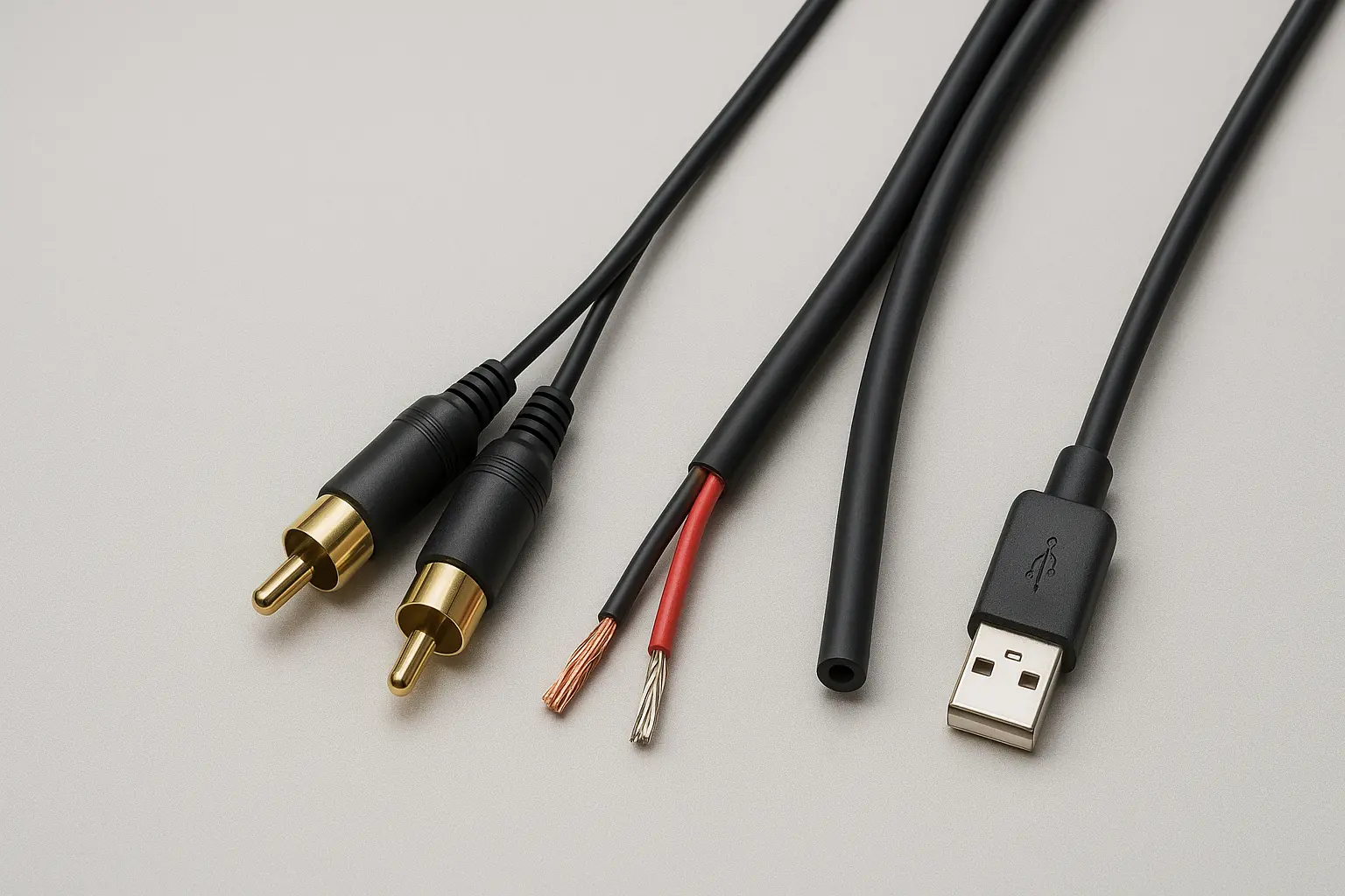
- Standard colorshelp assembly lines: red (right audio), white/black (left audio), yellow (composite video), orange (S/PDIF).
- Manufacturing projects should confirm MOQ, plating material, and test cyclesduring the quotation stage.
- Quality checksinclude contact resistance, insulation resistance, insertion force, and RoHS screening.
- Current supply-chain pressure means new tooling plus volume orders can stretch delivery windows past 40 weeks.
- Introduction
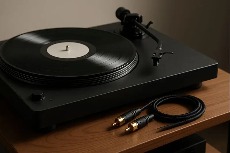
If you build or source audio-visual hardware, you will work with RCA jacks sooner or later. They sit on turntables, set-top boxes, guitar pedals, and even test gear. This article answers the question “what are RCA jacks” while giving engineering teams the detail they need for drawings, BOMs, and purchasing plans.
- What Are RCA Jacks?
An RCA jack is the female half of a two-part, unbalanced coaxial connector system. The jack’s center socket carries signal while the shell ties to ground. The male half—called the RCA plug—mates by friction. Variants appear under names such as phono connector, cinch connector, or simply A/V jack.
Because the design is simple, low-cost, and small, it remains common in consumer gear. An RCA jack on a PCB usually follows a through-hole footprint, though surface-mount parts exist for high-speed placement lines.
- A Brief History
|
Year |
Milestone |
Note |
|
1937 |
First internal use in RCA U-109 radio/phonograph |
Service technicians could unplug modules without soldering |
|
1940s |
Rear-panel jacks on tabletop radios |
Allowed buyers to attach external record players |
|
1950s |
Adoption in hi-fi amplifiers |
Stereo boom drove demand for low-noise interconnects |
|
1956 |
Composite video through yellow jack |
Home video equipment adopted the format |
|
1990s |
Component (Y Pb Pr) color trio |
Higher definition without new connectors |
- Anatomy and Key Specs
4.1 Mechanical Features
|
Feature |
Typical Value |
Purpose |
|
Center pin Ø |
3.175 mm |
Carries signal |
|
Shell Ø |
8.25 mm |
Ground and shield |
|
Max cable Ø |
7 mm |
Accepts common coax |
|
Mating cycles |
100–5,000 |
Durability grade |
|
Mating force |
0.5–3 kgf |
User feel + signal integrity |
Material choices influence cost and performance. Brass with nickel works for entry-level jobs; copper alloy with 15 µin gold resists oxidation on premium SKUs.
4.2 Electrical Figures
- Current: up to 1 A at 12 V DC (typical consumer use).
- Contact resistance: 30 mΩ initial, 80 mΩ after life testing.
- Insulation resistance: ≥100 MΩ at 500 V DC.
- Withstand voltage: 500 V AC for 60 s.
- Impedance:
- Audio: not tightly specified, usually 50–100 Ω.
- Composite or S/PDIF: target 75 Ω; real-world parts often land near 45–60 Ω because of geometry limits.
Thin-wall shells and tighter dielectric spacing improve real impedance but add cost.

- Color Coding and Signal Roles
|
Color |
Primary Use |
Extra Notes |
|
Red |
Right-channel audio |
Always paired with white or black |
|
White / Black |
Left-channel audio |
Black appears on some Asian product lines |
|
Yellow |
Composite video |
PAL/NTSC SD video path |
|
Orange |
S/PDIF digital audio |
0.5 V pp coax spec |
|
Green |
Y (luma) component |
HD capable |
|
Blue |
Pb (Cb) component |
|
|
Red |
Pr (Cr) component |
Shares shell color with right audio—label parts clearly |
During line builds, matching colors prevents mix-ups and helps inspection teams catch faults quickly.
- Manufacturing and Supply Chain Points

6.1 MOQ and Tooling
Standard footprints often start at 1,000–5,000 pcs. Unique plating, angle, or color can push MOQ above 10,000 pcs as the factory amortizes new tooling and trim. First samples usually ship two weeks after PO; hard tools need another five to six weeks.
6.2 Lead-Time Drift
Copper prices, galvanic plating slots, and port congestion add uncertainty. Many buyers now place blanket orders six to eight months ahead to lock slot time. If you need a fresh mold, pad the schedule by another month.
6.3 Quality Steps
- Incoming: X-ray plating thickness, plastic resin certificate check.
- In-process: Pin diameter gauge, insertion force test each shift.
- Burn-in: 500 cycle plug/unplug on sample lot.
- Final: Continuity scan, high-pot, optics for dents.
- Compliance: RoHS, REACH, plus any customer-specific requests.
- RCA Jack vs. Other Connectors
|
Connector |
Signal Nature |
Locking |
Max Distance (typ.) |
Unit Cost (bulk) |
|
RCA |
Unbalanced |
Friction |
2–3 m audio |
Low |
|
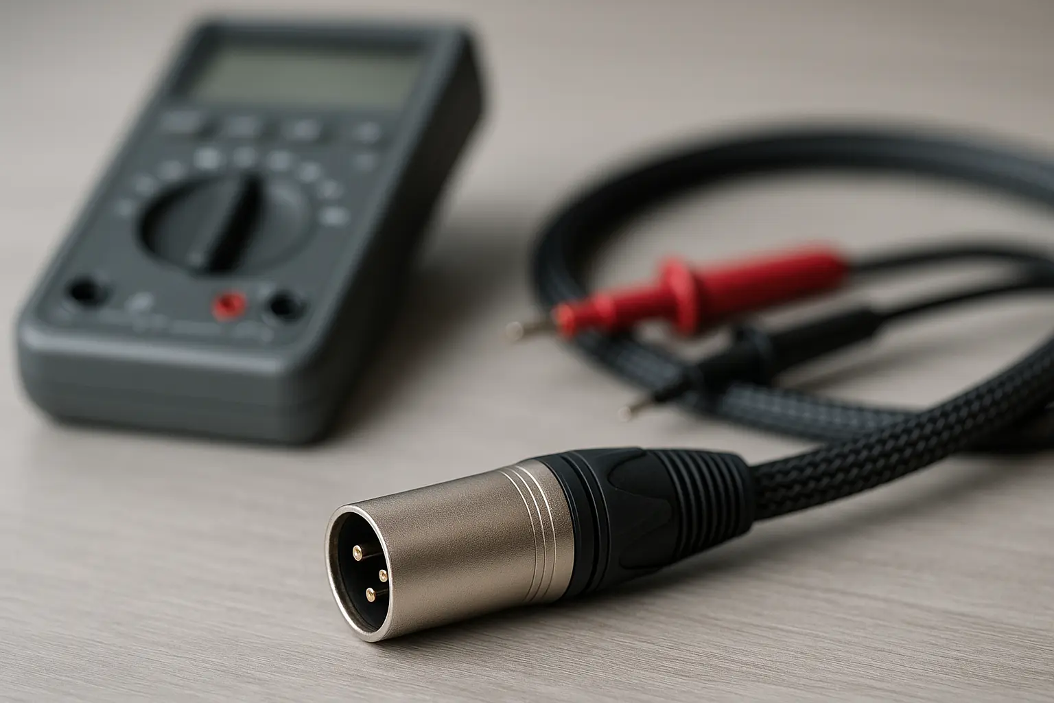
XLR |
Balanced |
Latch |
100 m+ audio |
Mid |
|
BNC |
75 Ω |
Bayonet |
50 m SDI |
Mid |
|
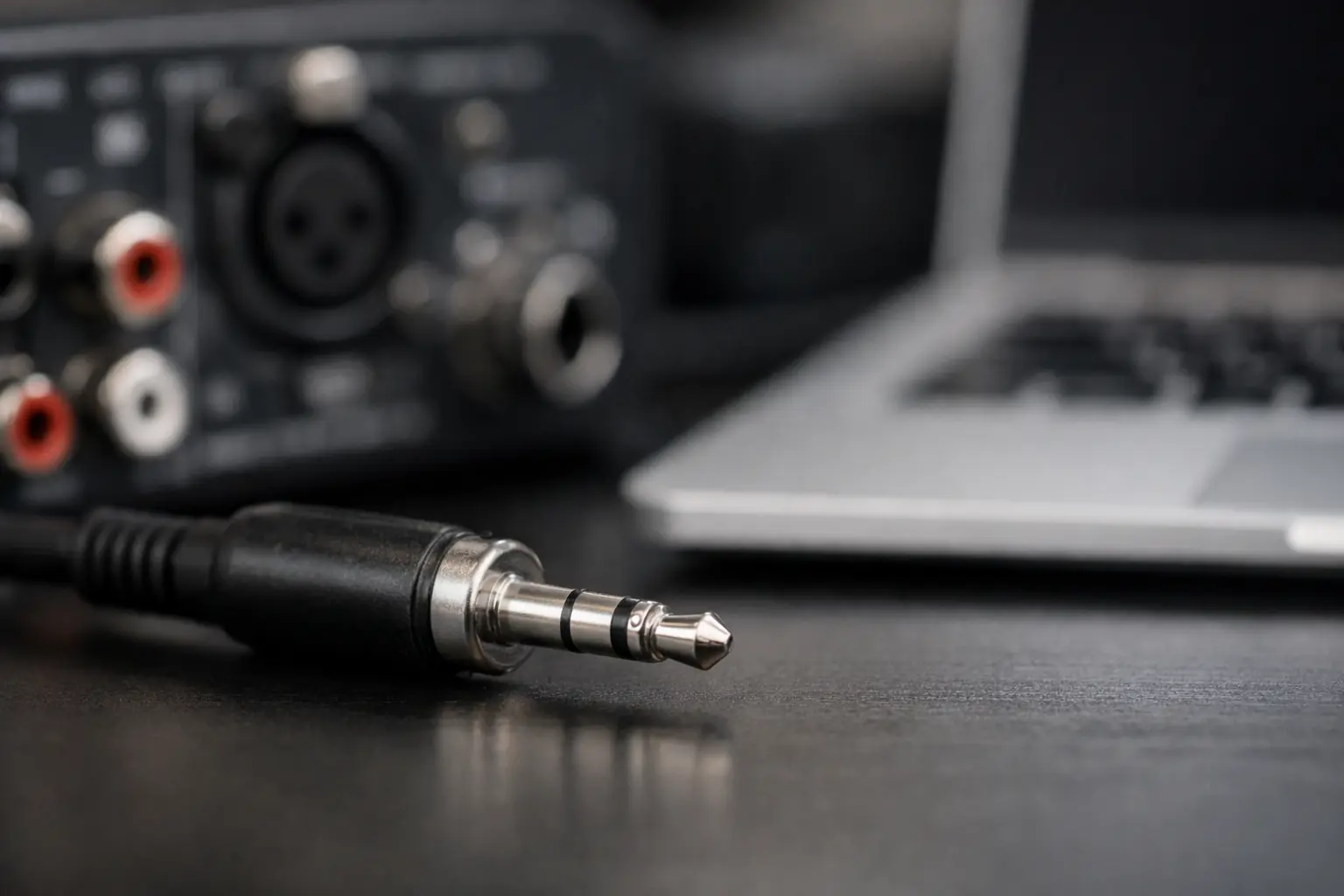
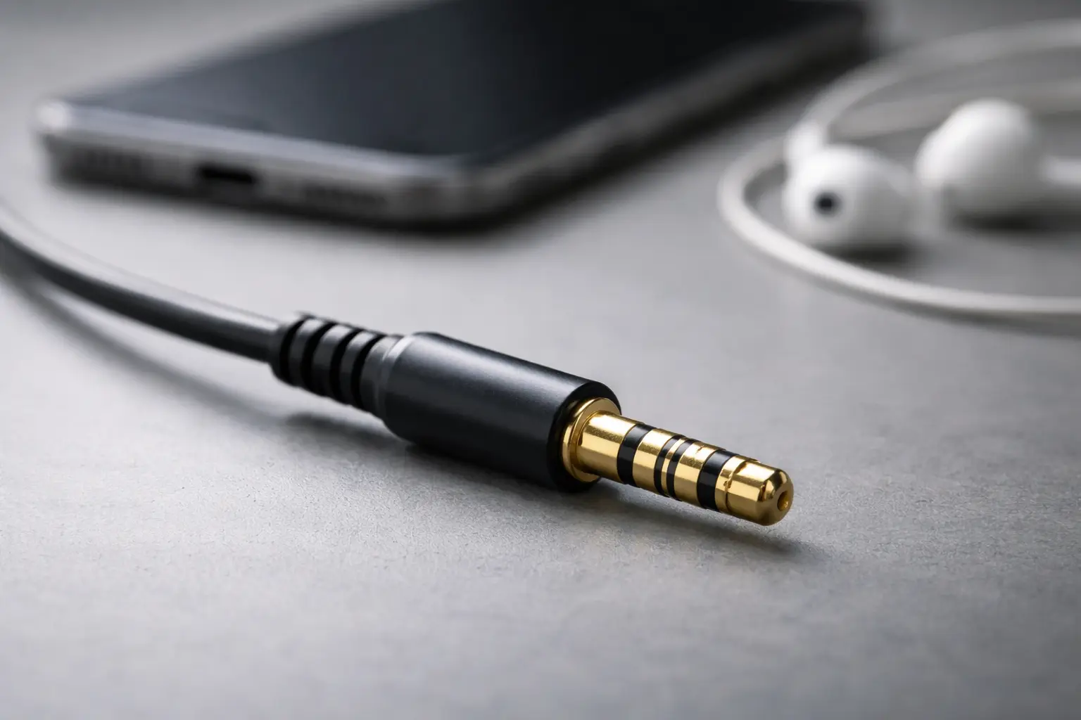
3.5 mm TRS |
Unbalanced |
Friction |
1–2 m |
Very low |
RCA shines where price and familiarity sit above bandwidth. For long runs or strict impedance, a BNC or XLR wins.
- Quality Tests in Detail
|
Test |
Method |
Pass Limit |
Why It Matters |
|
Contact resistance |
20 mV, 100 mA four-wire |
≤30 mΩ |
Low loss |
|
Insulation resistance |
500 V DC, 1 min |
≥100 MΩ |
Prevent crosstalk |
|
Dielectric strength |
500 V AC, 60 s |
No flashover |
Safety |
|
Salt fog |
48 h, 5% NaCl |
No red rust |
Marine / auto gear |
|
Mating cycles |
Motorized rig |
No plating wear through |
Durability |
Document these lines in the control plan so the factory’s QC team and your auditors share one language.
- Sourcing Tips for Project Teams

- Share the mating plug spec. A jack optimized for a slim Hi-Fi cable may not grip a chunky car-audio plug.
- Lock plating early. Swapping nickel for gold late in the schedule invites requalification.
- Ask for impedance plotsif video or S/PDIF signals cross 10 ft.
- Check packaging(tape-and-reel, tray, or bulk) to fit with SMT or wave lines.
- Keep a golden sample kitin the lab; run plug-fit spot checks when reels arrive.
- FAQ
-
Why does my 75 Ω video spec sometimes measure below 60 Ω on an RCA jack?
Geometry limits make a perfect match tough; most consumer jacks settle between 45 Ω and 60 Ω. -
Can I run HDMI signals through an RCA jack?
HDMI needs differential pairs and high bandwidth that the jack cannot carry. -
What is the typical plating thickness for mid-tier audio gear?
Nickel or tin at 100–150 µin on shell, same or flash gold on pin. -
Do panel-mount and board-mount jacks share footprints?
Not always. Board-mount uses solder legs; panel-mount relies on nut threads. -
How many mating cycles can a budget jack survive?
About 100. Premium units with gold can reach 5,000 cycles. -
Is S/PDIF over RCA truly “digital”?
It carries a bi-phase coded stream at 0.5 V pp per IEC 60958-3. -
Why does the same red shell appear for audio and component video?
Legacy color sharing; always check the printed label to avoid cross-wiring. -
What storage conditions keep inventory fresh?
10 °C–30 °C, <70% RH, sealed bags with desiccant for more than six months. -
How do I avoid whisker growth on tin-plated jacks?
Specify matte tin over copper and keep finishes under 3 µm. -
Are recycled plastics safe for housings?
Regrind up to 10% is common, but always request UL flammability data.
Reference List
- “What is a RCA Connector?” – Connector Supplier.
- “RCA connector” – Wikipedia.
- “A Complete Guide to RCA Connectors” – RS Components.
- “Red, White, And Yellow Cables: What Are They Called & Used For” – SlashGear.
- “Choose Between RCA (Unbalanced) and XLR (Balanced)” – NuPrime Audio.
- “Is There Really a True 75 Ohm RCA Plug?” – Blue Jeans Cable.
- “Quality Control” – Rasantek Audio.
- “Connector Manufacturing Process Delays” – Amerline.
- “MOQ vs. MPQ in Connectors” – LLT-CONN.
- “Supply Chain Slowdowns in Pro Audio” – AV Network.