


The Definitive Guide to XLR Connector Pinout Diagrams & Wiring Standards
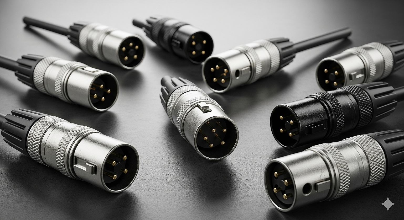
Walk into any recording studio in Los Angeles or a live venue in Nashville, and you’ll find XLR connectors everywhere. These three-pin workhorses handle everything from pristine vocal recordings to thunderous bass lines. If you’re an audio engineer in New York or a producer setting up shop in Austin, knowing XLR connector pinout diagrams and wiring standards isn’t just helpful—it’s essential.
This guide gives you the full picture: the universal 3-pin XLR pinout, multi-pin variations, practical wiring diagrams, and how to solve real-world problems. We’ll cover AES standards, balanced vs. unbalanced audio, DMX lighting, and common troubleshooting methods.
The Foundation: Understanding the 3-Pin XLR Connector Pinout
The AES Standard (AES14-1992): Why Pin 2 is “Hot” Worldwide
Professional audio relies on the AES14-1992 standard, which fixed the universal pinout for 3-pin XLR connectors in balanced audio. This ensures a Shure microphone in California works perfectly with an SSL console in Germany.
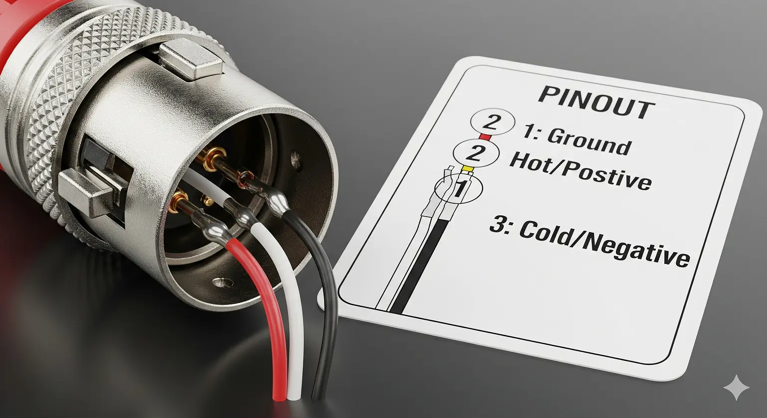
Standard 3-Pin XLR Pinout Diagram:
|
Pin |
Function |
|
1 |
Ground/Shield |
|
2 |
Positive/Hot (+) |
|
3 |
Negative/Cold (–) |
Before this standard, chaos reigned: some American manufacturers used “Pin 3 hot” while Europe and Japan favored “Pin 2 hot.” Mixing the two created phase cancellation—thin drum overheads, hollow guitars, and frustrated engineers. AES14-1992 (later ANSI S4.48-1992) ended the confusion.
How Balanced Audio Works: Common-Mode Rejection
Balanced audio separates amateur setups from professional installations. Those three pins aren’t random—they create noise rejection that makes long cable runs possible.
- Signal Split: The audio signal is duplicated, with one inverted 180°.
- Noise Pickup: Both wires pick up identical interference from power lines and lights.
- Noise Cancel: At the destination, the inverted signal is flipped back. The audio doubles (+6dB), while the noise cancels.
That’s why you can run XLR cables 200 feet across a venue without buzz or hum—something impossible with unbalanced TS or RCA.
Beyond Basics: Multi-Pin XLR Connector Variations
5-Pin XLR Pinout: Stereo Audio and DMX Lighting
Stereo Microphone Applications:
|
Pin |
Function |
|
1 |
Common Ground/Shield |
|
2 |
Left Hot (+) |
|
3 |
Left Cold (–) |
|
4 |
Right Hot (+) |
|
5 |
Right Cold (–) |
High-end stereo microphones in film scoring and classical venues often use this wiring.
DMX512 Lighting Control (ANSI E1.11-2008):
|
Pin |
Function |
|
1 |
Signal Ground |
|
2 |
Data 1– (Main) |
|
3 |
Data 1+ (Main) |
|
4 |
Data 2– (Backup) |
|
5 |
Data 2+ (Backup) |
4-Pin XLR Pinout: Intercom and DC Power
Professional Intercom Systems:
- Pin 1: Mic Ground
- Pin 2: Mic Signal (Hot)
- Pin 3: Headphone Ground
- Pin 4: Headphone Signal (Hot)
DC Power Applications:
- Pin 1: Ground (0V)
- Pin 4: +12V DC (Pins 2 & 3 unused)
Used widely in broadcast, film, and location recording.
7-Pin XLR Pinout: Tube Microphones
Seven-pin XLR connectors link tube microphones to their power supplies. They carry heater, plate, and polarization voltages. Warning: No universal standard—each manufacturer uses a different scheme. Always check documentation.
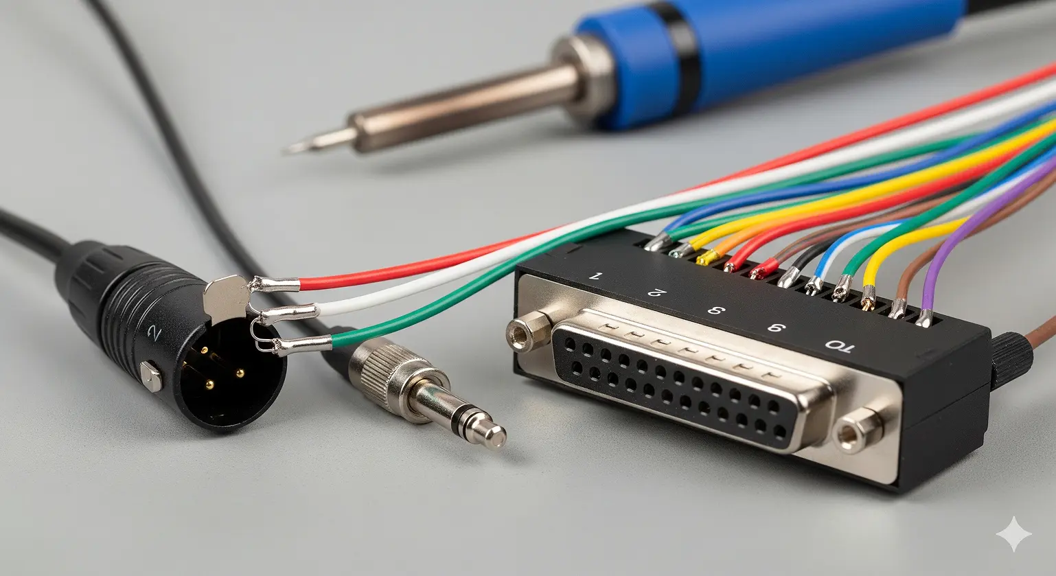
Practical XLR Wiring Diagrams
Balanced: XLR to TRS
- XLR Pin 1 → TRS Sleeve (Ground)
- XLR Pin 2 → TRS Tip (Hot)
- XLR Pin 3 → TRS Ring (Cold)
Maintains noise rejection and full balanced performance.
Unbalanced: XLR to TS/RCA
- XLR Pin 2 → Tip (Signal)
- XLR Pins 1 & 3 → Sleeve (Ground)
Downside: –6dB signal drop and no noise rejection. Keep runs short.
DB25 Pinout (TASCAM Analog Standard)
Adopted by Avid, Universal Audio, and others for multi-channel connections.
Example (Channels 1–3):
- Ch 1: Pin 14 (Hot), Pin 1 (Cold), Pin 13 (Ground)
- Ch 2: Pin 2 (Hot), Pin 15 (Cold), Pin 3 (Ground)
- Ch 3: Pin 16 (Hot), Pin 4 (Cold), Pin 17 (Ground)
Troubleshooting Common XLR Problems
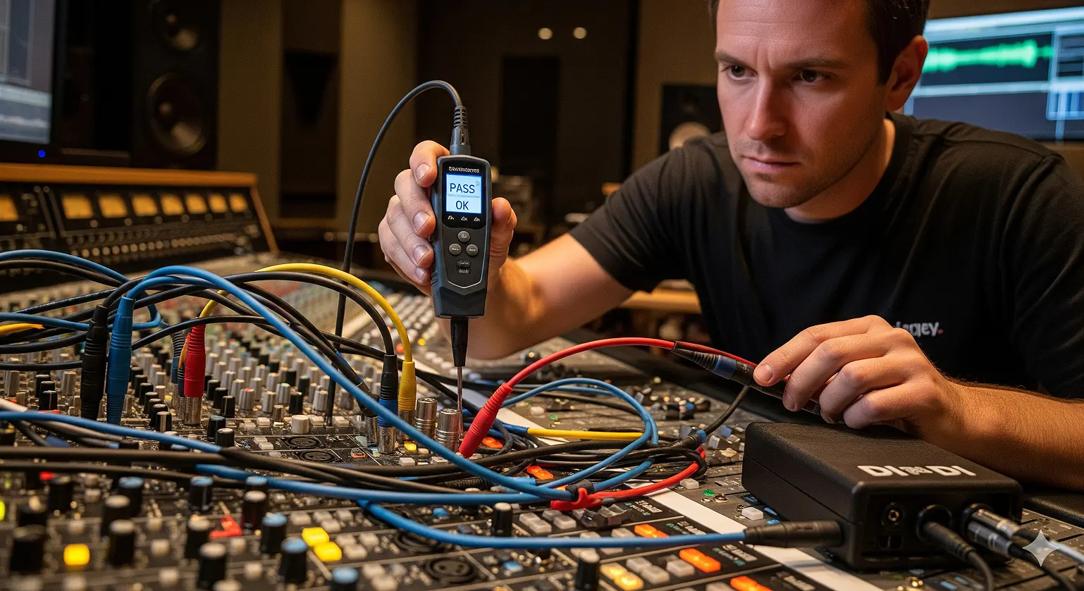
Polarity Reversal (“Out of Phase”)
Symptoms:
- Thin or hollow sound with multiple mics
- Bass disappears in mono
Fixes:
- Use the polarity (Ø) switch on your console
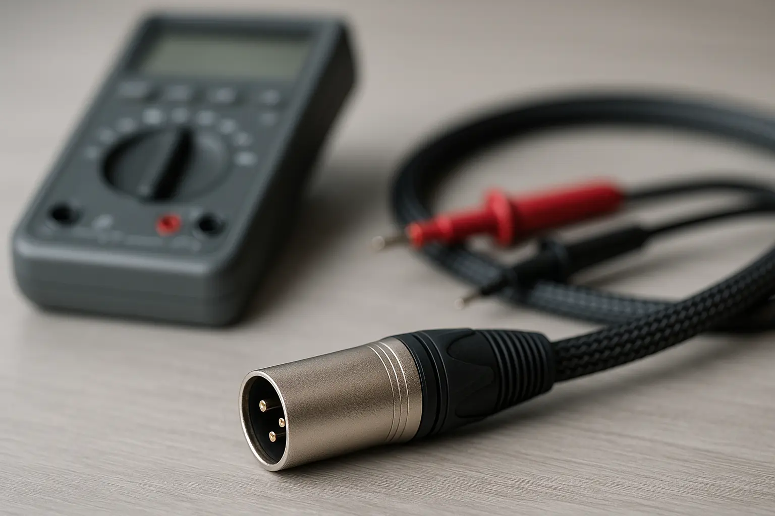
- Test with a cable tester
- Listen for low-end returning when corrected
Ground Loop Hum (60 Hz)
Common in US setups due to the power grid.
Fixes:
- Connect all gear to the same circuit
- Use DI boxes with ground lift switches
- Employ quality US-voltage power conditioners
- Use isolation transformers if needed
Frequently Asked Questions (FAQ)
Q1: What is the standard 3-pin XLR pinout?
A: Pin 1 = Ground, Pin 2 = Hot (+), Pin 3 = Cold (–).
Q2: Can I use mic XLR cables for DMX lighting?
A: No. DMX requires 110-ohm impedance cable. Using mic cables causes flicker and may damage gear.
Q3: What’s the difference between XLR and RCA?
A: XLR is balanced and noise-resistant for long runs. RCA is unbalanced and should be under 20 feet.
Q4: Will plugging a mic into a line-level XLR input cause damage?
A: No damage, but the signal will be too weak. Microphones need preamps.
Q5: What is the “Pin 1 Problem”?
A: Older gear tied Pin 1 directly to chassis, creating ground loops. Modern gear isolates it properly, but vintage gear may still cause issues.
Wrapping Up
Understanding XLR connector pinout diagrams and wiring standards separates amateurs from professionals. The AES 3-pin standard ensures compatibility, while multi-pin XLR connectors power everything from DMX lighting to tube microphones.
Whether you’re wiring a home studio in Nashville, upgrading a venue in Chicago, or troubleshooting in Los Angeles, correct XLR wiring delivers reliability and pristine audio. Good cables and proper pinouts aren’t glamorous, but they are the backbone of professional audio.
Citations
- AES14-1992 (s2019): AES standard for professional audio equipment – XLR polarity.
- Amphenol Audio: XLR Wiring Information.
- Sescom, Inc.: XLR Pinouts & Pin 2 Hot.
- Wikipedia: “XLR connector.”
- Aviom, Inc.: DB25 Pinout (Tascam Standard).
- ANSI E1.11-2008: DMX512-A Standard.
- Boxcast: “Balanced vs. Unbalanced Audio.”
- Gearit: “Ground Loops in Audio Systems.”
- Canford: “XLR 4-Pin Wiring for DC Power.”
- Live Sound (NZ): Signal Cable Wiring Diagrams.